Sunday, August 4, 2013
Nokia 6270 PCB board layout.
Nokia 6270 PCB board layout
The front and back side layout of components on Nokia 6270 main PCB board. to be used as mobile phone repair manual on Nokia 6270.
Saturday, August 3, 2013
SIMPLE 230V LED DRIVER Circuits ..
230V LED Driver circuit without
transformer. Here i am using 5 led's you can
increase the count at your convineance. Due to the absence of Transformers we
can reduce the cost and size of the circuit considerably. As we all know LED's
are Cheap, efficient and cool device with low power consumption. So we can
reduce our electricity bills to a great extent.
The circuit is powered by 230V 50Hz ac supply, so be careful while troubleshooting this project.
Led's commonly works only in DC, so
we have to convert the alternating current to direct current and step down to a
safe value before applying to the led sequence.
The circuit mainly consisting of 5 led bulbs, a bridge rectifier and a filtering network with voltage regulator.
The bridge rectifier is used to convert alternating current (AC) to pulsating DC. It is made possible by means of rectifying diodes (D1 to D4 1N4007)
The filtering is made possible by means of a capacitor (47uF). It is used to eliminate the ripples coming from rectifier circuit.
After regulating the filtered voltage using a zener diode, we get an almost direct current suitable for LED's.
The circuit mainly consisting of 5 led bulbs, a bridge rectifier and a filtering network with voltage regulator.
The bridge rectifier is used to convert alternating current (AC) to pulsating DC. It is made possible by means of rectifying diodes (D1 to D4 1N4007)
The filtering is made possible by means of a capacitor (47uF). It is used to eliminate the ripples coming from rectifier circuit.
After regulating the filtered voltage using a zener diode, we get an almost direct current suitable for LED's.
230V LED Driver circuit without transformer.
Here i am using 5 led's you can increase the count at your convineance.
Due to the absence of Transformers we can reduce the cost and size of
the circuit considerably. As we all know LED's are Cheap, efficient and
cool device with low power consumption. So we can reduce our electricity
bills to a great extent.
The circuit is powered by 230V 50Hz ac supply, so be careful while troubleshooting this project.
Led's commonly works only in DC, so we have to convert the alternating
current to direct current and step down to a safe value before applying
to the led sequence.
The circuit mainly consisting of 5 led bulbs, a bridge rectifier and a filtering network with voltage regulator.
The bridge rectifier is used to convert alternating current (AC) to pulsating DC. It is made possible by means of rectifying diodes (D1 to D4 1N4007)
The filtering is made possible by means of a capacitor (47uF). It is used to eliminate the ripples coming from rectifier circuit.
After regulating the filtered voltage using a zener diode, we get an almost direct current suitable for LED's.
- See more at: http://www.mycircuits9.com/2012/08/230v-led-driver-circuit.html#sthash.zRwA5uPL.dpuf
The circuit is powered by 230V 50Hz ac supply, so be careful while troubleshooting this project.
Led's commonly works only in DC, so we have to convert the alternating
current to direct current and step down to a safe value before applying
to the led sequence.The circuit mainly consisting of 5 led bulbs, a bridge rectifier and a filtering network with voltage regulator.
The bridge rectifier is used to convert alternating current (AC) to pulsating DC. It is made possible by means of rectifying diodes (D1 to D4 1N4007)
The filtering is made possible by means of a capacitor (47uF). It is used to eliminate the ripples coming from rectifier circuit.
After regulating the filtered voltage using a zener diode, we get an almost direct current suitable for LED's.
- See more at: http://www.mycircuits9.com/2012/08/230v-led-driver-circuit.html#sthash.zRwA5uPL.dpuf
230V LED Driver circuit without transformer.
Here i am using 5 led's you can increase the count at your convineance.
Due to the absence of Transformers we can reduce the cost and size of
the circuit considerably. As we all know LED's are Cheap, efficient and
cool device with low power consumption. So we can reduce our electricity
bills to a great extent.
The circuit is powered by 230V 50Hz ac supply, so be careful while troubleshooting this project.
Led's commonly works only in DC, so we have to convert the alternating
current to direct current and step down to a safe value before applying
to the led sequence.
The circuit mainly consisting of 5 led bulbs, a bridge rectifier and a filtering network with voltage regulator.
The bridge rectifier is used to convert alternating current (AC) to pulsating DC. It is made possible by means of rectifying diodes (D1 to D4 1N4007)
The filtering is made possible by means of a capacitor (47uF). It is used to eliminate the ripples coming from rectifier circuit.
After regulating the filtered voltage using a zener diode, we get an almost direct current suitable for LED's.
- See more at: http://www.mycircuits9.com/2012/08/230v-led-driver-circuit.html#sthash.zRwA5uPL.dpuf
The circuit is powered by 230V 50Hz ac supply, so be careful while troubleshooting this project.
Led's commonly works only in DC, so we have to convert the alternating
current to direct current and step down to a safe value before applying
to the led sequence.The circuit mainly consisting of 5 led bulbs, a bridge rectifier and a filtering network with voltage regulator.
The bridge rectifier is used to convert alternating current (AC) to pulsating DC. It is made possible by means of rectifying diodes (D1 to D4 1N4007)
The filtering is made possible by means of a capacitor (47uF). It is used to eliminate the ripples coming from rectifier circuit.
After regulating the filtered voltage using a zener diode, we get an almost direct current suitable for LED's.
- See more at: http://www.mycircuits9.com/2012/08/230v-led-driver-circuit.html#sthash.zRwA5uPL.dpuf
Thursday, June 6, 2013
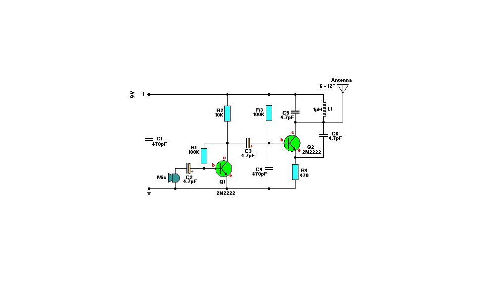
FM-Transmitter Circuit.
Nothing
critical here. To get a bit of tuning out of the coil you could put a
4-40pF trimmer capacitor (optional) parallel over the 1 μH
coil, L1. C1/C4 and C5/C6 are ceramic capacitors, preferably NPO (low
noise) types. C2/C3 are electrolytic or can be tantalum types. The
antenna is nothing more than a piece of 12" wire or a piece of piano
wire from 6" to 12".
To
find the signal on your receiver, make sure there is a signal coming
into the microphone, otherwise the circuit won't work. I use an old
mechanical alarm clock (you know, with those two large bells on it). I
put this clock by the microphone which picks up the loud tick-tock. I'm
sure you get the idea... Or you can just lightly tap the microphone
while searching for the location of the signal on your receiver.
Parts List
R1,R3 = 100K
R2 = 10K
R4 = 470 ohm
C1,C4 = 470pF
C2,C3 = 4.7μF, 16V, electrolytic
C5,C6 = 4.7pF
C7 = 4-40pF trimmer cap (optional, see text)
L1 = 1μH
Q1,Q2 = 2N2222, NPN transistor
Mic = Electret Microphone
B1 = 9 Volt, Alkaline battery
Wednesday, June 5, 2013
Saturday, June 1, 2013
Thursday, May 30, 2013
10Watt Audio Amplifier with Bass boost circuit.
Circuit diagram
parts list
P1_________________22K Log.Potentiometer (Dual-gang for stereo)
P2________________100K Log.Potentiometer (Dual-gang for stereo)
R1________________820R 1/4W Resistor
R2,R4,R8____________4K7 1/4W Resistors
R3________________500R 1/2W Trimmer Cermet
R5_________________82K 1/4W Resistor
R6,R7______________47K 1/4W Resistors
R9_________________10R 1/2W Resistor
R10__________________R22 4W Resistor (wirewound)
C1,C8_____________470nF 63V Polyester Capacitor
C2,C5_____________100µF 25V Electrolytic Capacitors
C3,C4_____________470µF 25V Electrolytic Capacitors
C6_________________47pF 63V Ceramic or Polystyrene Capacitor
C7_________________10nF 63V Polyester Capacitor
C9________________100nF 63V Polyester Capacitor
D1______________1N4148 75V 150mA Diode
IC1_____________NE5532 Low noise Dual Op-amp
Q1_______________BC547B 45V 100mA NPN Transistor
Q2_______________BC557B 45V 100mA PNP Transistor
Q3_______________TIP42A 60V 6A PNP Transistor
Q4_______________TIP41A 60V 6A NPN Transistor
J1__________________RCA audio input socket
Power supply circuit
Circuit diagram
Parts R11_________________1K5 1/4W Resistor
C10,C11__________4700µF 25V Electrolytic Capacitors
D2________________100V 4A Diode bridge
D3________________5mm. Red LED
T1________________220V Primary, 12 + 12V Secondary 24-30VA Mains transformer
PL1_______________Male Mains plug
SW1_______________SPST Mains switch .Electronics Circuit Application
Subscribe to:
Posts (Atom)
Popular Posts
-
Antenna Point : The point where antenna is connected is called antenna point. It is normally located at the top of the PCB of a mobile pho...
-
Here is a circuit Power Amplifier with output power of more than 600 Watt speakers with impedance of 4 Ohm. Power Amplifier circuit wi...
-
Adjustable 0-30V 2A Laboratory DC Power Supply PCB of Cheap adjustable 0-30V 2A Laboratory DC Power Supply This 0-30V...
-
STK465 - 30 watt Stereo Power Amplifier STK465 - 30 watt Stereo Power Amplifier Source: http://sharingmanual.blogspot.com/2012/08/stk46...
-
Nokia 1600 Ringer Buzzer repairing solution.Nokia 1600 Ringer Buzzer Mobile Repair diagram pictures Service Tips and Tr...
-
Samsung Galaxy series is known to be one of the finest smart phone ranges that exist today, and this is mainly because its features have su...
-
Circuit Parts List: R1____________3K3 1/2W Resistor C1___________10nF 1000V Polyester Capacitor C2,C3______4700µF 50V Electro...
-
What can be done to increase available audio power amplifier? The answer is either decrease load impedance or increase supply voltage. The ...
-
Build this wi-fi antenna to build when you want results FAST and have just a few inexpensive tools and supplies available. It will greatly...