
Monday, August 26, 2013
Saturday, August 24, 2013
4AA Battery Powered 12V LED Spotlight - 12V Power Supply circuits
Most of the electronic projects and electronic devices are required 12V
power source; typically a 12V sealed lead acid battery or AC powered
power supply. These are typically large, heavy, difficult to handle, and
expensive; portability is less. The best solution is to use a DC-DC
Step up converter. These types of convertors are inexpensive, light
weight and easy to use. Also provides power management and easy to work
with renewable energy sources.

The input power source could be rechargeable AA batteries. Let’s make an environment friendly 12V/130mA power supply!
 100uf Electrolytic Capacitor 16V C1,C2 -2
100Ohms Resistor 1/4W R1,R2 -2
1N5817 Schotkey Diode 1A D1- 1
150UH Radial Power Inductor 1A IND1- 1
LT1073CN8-12 IC DIP Package IC1 -1
IC Base 8 PIN -1
PCB to Wire Connector- 2
4AA Battery Holder- 1
The heart of this application is LT1073 IC. It is a power management IC which steps up low voltage into high voltage by switching.
First I etched four PCBs for the prototype using a PCB design software and some other tools. The PCBs are very small (4cmX2cm) because components need to be solder as close as to the IC; because of the performance issues. I made ground copper track as wide as possible.
Now my prototype works fine and I decided to make the PCB in large quantity. I did some changes and sent my PCB file to a local PCB production company and first I got 100 pieces of PCBs. The PCBs are in good quality with solder spots and copper shield; easy to solder

Ratings:
Operating Hours: 20,000 hours
Operating Voltage: 12V
Intensity: 55,000 mcd
Forward Current: 80 mA @ 12Vdc
Viewing Angle: 30 Degrees
Absolute Maximum Ratings:
Operating Voltage(V): 14 V
Operating Temperature (Topr): -25oC to +85oC
Storage Temperature (Ts): -35oC to +100oC
The input power source could be rechargeable AA batteries. Let’s make an environment friendly 12V/130mA power supply!
100Ohms Resistor 1/4W R1,R2 -2
1N5817 Schotkey Diode 1A D1- 1
150UH Radial Power Inductor 1A IND1- 1
LT1073CN8-12 IC DIP Package IC1 -1
IC Base 8 PIN -1
PCB to Wire Connector- 2
4AA Battery Holder- 1
The heart of this application is LT1073 IC. It is a power management IC which steps up low voltage into high voltage by switching.
First I etched four PCBs for the prototype using a PCB design software and some other tools. The PCBs are very small (4cmX2cm) because components need to be solder as close as to the IC; because of the performance issues. I made ground copper track as wide as possible.
Now my prototype works fine and I decided to make the PCB in large quantity. I did some changes and sent my PCB file to a local PCB production company and first I got 100 pieces of PCBs. The PCBs are in good quality with solder spots and copper shield; easy to solder
Ratings:
Operating Hours: 20,000 hours
Operating Voltage: 12V
Intensity: 55,000 mcd
Forward Current: 80 mA @ 12Vdc
Viewing Angle: 30 Degrees
Absolute Maximum Ratings:
Operating Voltage(V): 14 V
Operating Temperature (Topr): -25oC to +85oC
Storage Temperature (Ts): -35oC to +100oC
Thursday, August 22, 2013
variable voltage adjustable power supply circuits
Features:
Regulated Adjustable Voltage out 2-30VDC
High Current Output 5A (based on transformer selection).
Adjustable Current Limit
Can be used as a variable current supply.
Based on LM317 Voltage Regulator.
Built in protection diodes
Speed controlled fan connection (based on current draw).
Current meter connection (0.1V/1A).
 Circuit Diagram


Regulated Adjustable Voltage out 2-30VDC
High Current Output 5A (based on transformer selection).
Adjustable Current Limit
Can be used as a variable current supply.
Based on LM317 Voltage Regulator.
Built in protection diodes
Speed controlled fan connection (based on current draw).
Current meter connection (0.1V/1A).
Features universal capcitor
mounting/spacing to allow various
capacitors to fit. Mounting pattern that fits TO-200 or
TO-218/247 for pass transistor and transistor used for current limit
circuit. Fan connection uses connection compatible with standard
PC fan connection; allowing use of PC heatsink fan combination.
MOBILE PHONE BATTERY CHARGER CIRCUITS.
Mobile phone chargers available in the market are quite expensive. The circuit presented here comes as a low-cost alternative to charge mobile telephones/battery packs with a rating of 7.2 volts, such as Nokia 6110/6150.

Sunday, August 18, 2013
12V to 220V inverte 500W Circuits
Attention: This Circuit is using high voltage that is lethal. Please take appropriate precautions
Using this circuit you can convert the 12V dc in to the 220V Ac. In this circuit 4047 is use to generate the square wave of 50hz and amplify the current and then amplify the voltage by using the step transformer.

Using this circuit you can convert the 12V dc in to the 220V Ac. In this circuit 4047 is use to generate the square wave of 50hz and amplify the current and then amplify the voltage by using the step transformer.
Saturday, August 17, 2013
AC Powered LED.
A long time ago I found a little schematic on internet on how to
power a LED from an AC Line.
I tested and modified it a little so now it works great.
You could use it as an power-on indicator for your waterpump or so. Also it can be used with whatever LED-color you like.
I tested and modified it a little so now it works great.
You could use it as an power-on indicator for your waterpump or so. Also it can be used with whatever LED-color you like.
I included the schematics for US or canadian 110-120V 60Hz AC
lines, as well as european or australian 230-240V 50Hz AC lines.
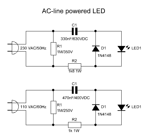
The capacitor is used to drop the voltage and the resistor to limit the inrush current.
Since the capacitor passes the current in both directions, a small diode is connected in parallel with the LED to provide a path for the negative half cycle and to limit the reverse voltage across the LED. The resistor value was chosen to limit the worst case inrush current to about 150mA which will drop to less than 30mA in a millisec as the capacitor charges.
The 0.47uF capacitor has an impedance of 5600 Ohms at 60Hz so the LED current is about 20mA half wave, or 10mA average (for the 230V version the impedance of the 0.33uF capacitor is 9600 Ohms at 50Hz which gives you also a LED current of about 10mA average)
Z = 1 / 2*Pi*f*C
Z = Impedance in Ohms
Pi = 3.14
f = frequency in Hertz
C = capacity in Farads)
C = capacity in Farads)
The capacitor must be a non-polarized type with a voltage rating of at least 250VDC or preferably more for 110V AC-lines, or at least 400VDC or preferably more for 230V AC-lines.
Resistor R1 discharges capacitor C1 in a few seconds after AC-line is disconnected. Remember that R1 must be able to withstand the full half wave peak AC-line voltage.
IMPORTANT: The circuit is powered from the AC line, so I will not be held responsible in any way for burned fingers, or melted fuses in your house. Isolate all connections with heat shrink.
Electronics Circuit Application
Tuesday, August 13, 2013
FM Transmitter Circuits - 4Transistors..
This circuit provides an FM modulated signal with an output power of around 500mW. The input microphone pre-amp is built around a couple of 2N3904 transistors (Q1/Q2), and audio gain is limited by the 5k preset trim potentiometer. The oscillator is a colpitt stage, frequency of oscillation governed by the tank circuit made from two 5pF ceramic capacitors and the L2 inductor. The output stage operates as a 'Class D' amplifier, no direct bias is applied but the RF signal developed across the 3.9uH inductor is sufficient to drive this stage. The emitter resistor and 1k base resistor prevent instability and thermal runaway in this stage.Electronics Circuit Application
TV Transmitter Circuit ..
This is a small TV transmitter circuit which transmits in VHF band, negative sound modulation and PAL video modulation. It is suitable in countries where the B and G system is used. Electronics Circuit Application
Sunday, August 11, 2013
High Gain Yagi Wi-Fi Antenna
Build this wi-fi antenna to build when you want results FAST and have just a few inexpensive tools
and supplies available. It will greatly extend your wi-fi range - well beyond the limits of the dipoles that
accompany most routers and some wireless adapters. When connected to a
USB wireless adapter
the performance is excellent. When connected to a
high powered wi-fi adapter,
the performance is astounding! Forget about building those overly hyped wi-fi cantennas - they don't
perform anywhere close to the yagi antennas depicted here.
Sometimes the perfect wi-fi antenna is the one that can be made in an hour's time, from inexpensive parts, and yet enables connections over moderate to long distances. The yagi wi-fi antenna design depicted here is exactly that! It is computer designed, made of wood and wire, and provides high gain and directivity. It is directional - favoring wi-fi signals in one direction and rejecting interference from the sides or behind the antenna. The 15 element wi-fi antenna provides over 15 dB of gain (multiplying your effective radiated power by 31), while the larger 20 element wi-fi antenna provides over 17 dB of gain (multiplying your effective radiated power power by 51). Front to back ratio for both antennas is about 22 dB.
Yagi wi-fi antennas can be rather difficult to make - elements must be precisely cutto the proper length, and spaced at the correct distance from otherelements, or the antenna doesn't work. Before good computer tools were available, a designer used various charts and tables to determine antenna dimensions. These days, however, much of the mind numbing calculation can be carried out in a split second. One excellent tool for crunching design numbers is the yagi antenna modeler, created by Kevin Schmidt (W9CF) and Michael Lee.
Saturday, August 10, 2013
Best Transformer less Power Supply Circuit Using IC LR645.
A very interesting yet super simple transformer less power supply circuit has been discussed here. In one of my earlier posts I provided a similar circuit but it utilized a high voltage capacitor for dropping the mains voltage to lower usable levels. Here we study how the mains voltage is controlled to 12 volts and 5 volts using just a single IC LR645G and some other supportive ordinary active semiconductors.
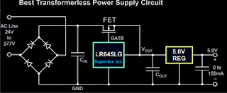
In short the circuit diagram may be understood in the following manner:
However one big drawback of eliminating the use of a transformer is the DANGER of high voltage shock that actively hangs with all the naked points of the circuit. Therefore extreme caution must be exercised while building and testing this circuit and other attached circuits.

Parts List
Diodes - 1N4007
Input Capacitor - 4.7uF/400V,
Output Capacitors are 1uF/25V
ICs are LR645LG and 7805,
FET - DN2540N5
In short the circuit diagram may be understood in the following manner:
- The high voltage AC mains is rectified by the bridge configuration using four diodes at the input.
- The rectified voltage is smoothed by the filter capacitor introduced just after the bridge network.
- The rectified, filtered high voltage is fed to the IC LR645LG, which effectively reduces the voltage to 15 volts at 3 mA.
- The FET pulls the 3 mA current output to 150 mA and feds it to the next stage which incorporates the 5 volt regulator stage.
However one big drawback of eliminating the use of a transformer is the DANGER of high voltage shock that actively hangs with all the naked points of the circuit. Therefore extreme caution must be exercised while building and testing this circuit and other attached circuits.
Parts List
Diodes - 1N4007
Input Capacitor - 4.7uF/400V,
Output Capacitors are 1uF/25V
ICs are LR645LG and 7805,
FET - DN2540N5
Electronics Circuit Application
Wednesday, August 7, 2013
50 Watt Amplifie small subwoofer Circuits..
This is a handy, easy to build general purpose 50 watt amp. The amp has
an input for a radio, TV, stereo or other line level device. It also has
a phono input for a record player, guitar, microphone or other
un-amplified source. With the addition of a low pass filter at the
input, it makes a great amp for a small subwoofer.

Tuesday, August 6, 2013


Monday, August 5, 2013
Galaxy S3 Audio Problem and solution..
Samsung Galaxy series is known to be one of the finest smart phone ranges that exist today, and this is mainly because its features have surely beaten a good number of industry giants. But nothing is flawless, no matter how better the technology is, as after some time it is going to start having some issues in it due to any of the reasons.

Sunday, August 4, 2013
Nokia 6270 PCB board layout.

The front and back side layout of components on Nokia 6270 main PCB board. to be used as mobile phone repair manual on Nokia 6270.
Saturday, August 3, 2013
SIMPLE 230V LED DRIVER Circuits ..

230V LED Driver circuit without
transformer. Here i am using 5 led's you can
increase the count at your convineance. Due to the absence of Transformers we
can reduce the cost and size of the circuit considerably. As we all know LED's
are Cheap, efficient and cool device with low power consumption. So we can
reduce our electricity bills to a great extent.
The circuit is powered by 230V 50Hz ac supply, so be careful while troubleshooting this project.
The circuit is powered by 230V 50Hz ac supply, so be careful while troubleshooting this project.

Led's commonly works only in DC, so
we have to convert the alternating current to direct current and step down to a
safe value before applying to the led sequence.
The circuit mainly consisting of 5 led bulbs, a bridge rectifier and a filtering network with voltage regulator.
The bridge rectifier is used to convert alternating current (AC) to pulsating DC. It is made possible by means of rectifying diodes (D1 to D4 1N4007)
The filtering is made possible by means of a capacitor (47uF). It is used to eliminate the ripples coming from rectifier circuit.
After regulating the filtered voltage using a zener diode, we get an almost direct current suitable for LED's.
230V LED Driver circuit without transformer.
Here i am using 5 led's you can increase the count at your convineance.
Due to the absence of Transformers we can reduce the cost and size of
the circuit considerably. As we all know LED's are Cheap, efficient and
cool device with low power consumption. So we can reduce our electricity
bills to a great extent.
The circuit is powered by 230V 50Hz ac supply, so be careful while troubleshooting this project.
 Led's commonly works only in DC, so we have to convert the alternating
current to direct current and step down to a safe value before applying
to the led sequence.
Led's commonly works only in DC, so we have to convert the alternating
current to direct current and step down to a safe value before applying
to the led sequence.
The circuit mainly consisting of 5 led bulbs, a bridge rectifier and a filtering network with voltage regulator.
The bridge rectifier is used to convert alternating current (AC) to pulsating DC. It is made possible by means of rectifying diodes (D1 to D4 1N4007)
The filtering is made possible by means of a capacitor (47uF). It is used to eliminate the ripples coming from rectifier circuit.
After regulating the filtered voltage using a zener diode, we get an almost direct current suitable for LED's.
- See more at: http://www.mycircuits9.com/2012/08/230v-led-driver-circuit.html#sthash.zRwA5uPL.dpuf
The circuit is powered by 230V 50Hz ac supply, so be careful while troubleshooting this project.
Led's commonly works only in DC, so we have to convert the alternating
current to direct current and step down to a safe value before applying
to the led sequence.The circuit mainly consisting of 5 led bulbs, a bridge rectifier and a filtering network with voltage regulator.
The bridge rectifier is used to convert alternating current (AC) to pulsating DC. It is made possible by means of rectifying diodes (D1 to D4 1N4007)
The filtering is made possible by means of a capacitor (47uF). It is used to eliminate the ripples coming from rectifier circuit.
After regulating the filtered voltage using a zener diode, we get an almost direct current suitable for LED's.
- See more at: http://www.mycircuits9.com/2012/08/230v-led-driver-circuit.html#sthash.zRwA5uPL.dpuf
230V LED Driver circuit without transformer.
Here i am using 5 led's you can increase the count at your convineance.
Due to the absence of Transformers we can reduce the cost and size of
the circuit considerably. As we all know LED's are Cheap, efficient and
cool device with low power consumption. So we can reduce our electricity
bills to a great extent.
The circuit is powered by 230V 50Hz ac supply, so be careful while troubleshooting this project.
Led's commonly works only in DC, so we have to convert the alternating
current to direct current and step down to a safe value before applying
to the led sequence.
The circuit mainly consisting of 5 led bulbs, a bridge rectifier and a filtering network with voltage regulator.
The bridge rectifier is used to convert alternating current (AC) to pulsating DC. It is made possible by means of rectifying diodes (D1 to D4 1N4007)
The filtering is made possible by means of a capacitor (47uF). It is used to eliminate the ripples coming from rectifier circuit.
After regulating the filtered voltage using a zener diode, we get an almost direct current suitable for LED's.
- See more at: http://www.mycircuits9.com/2012/08/230v-led-driver-circuit.html#sthash.zRwA5uPL.dpuf
The circuit is powered by 230V 50Hz ac supply, so be careful while troubleshooting this project.
Led's commonly works only in DC, so we have to convert the alternating
current to direct current and step down to a safe value before applying
to the led sequence.The circuit mainly consisting of 5 led bulbs, a bridge rectifier and a filtering network with voltage regulator.
The bridge rectifier is used to convert alternating current (AC) to pulsating DC. It is made possible by means of rectifying diodes (D1 to D4 1N4007)
The filtering is made possible by means of a capacitor (47uF). It is used to eliminate the ripples coming from rectifier circuit.
After regulating the filtered voltage using a zener diode, we get an almost direct current suitable for LED's.
- See more at: http://www.mycircuits9.com/2012/08/230v-led-driver-circuit.html#sthash.zRwA5uPL.dpuf
Subscribe to:
Posts (Atom)
Popular Posts
-
 Antenna Point : The point where antenna is connected is called antenna point. It is normally located at the top of the PCB of a mobile pho...
 -
 Here is a circuit Power Amplifier with output power of more than 600 Watt speakers with impedance of 4 Ohm. Power Amplifier circuit wi...
 -
 Adjustable 0-30V 2A Laboratory DC Power Supply PCB of Cheap adjustable 0-30V 2A Laboratory DC Power Supply This 0-30V...
 -
 STK465 - 30 watt Stereo Power Amplifier STK465 - 30 watt Stereo Power Amplifier Source: http://sharingmanual.blogspot.com/2012/08/stk46...
 -
 Nokia 1600 Ringer Buzzer repairing solution.Nokia 1600 Ringer Buzzer Mobile Repair diagram pictures Service Tips and Tr...
 -
 Samsung Galaxy series is known to be one of the finest smart phone ranges that exist today, and this is mainly because its features have su...
 -
 Circuit Parts List: R1____________3K3 1/2W Resistor C1___________10nF 1000V Polyester Capacitor C2,C3______4700µF 50V Electro...
 -
 What can be done to increase available audio power amplifier? The answer is either decrease load impedance or increase supply voltage. The ...
 -
 Build this wi-fi antenna to build when you want results FAST and have just a few inexpensive tools and supplies available. It will greatly...
