Each channel of LT3760 contains an accurate current sink with ±2% current matching. Output current for each channel can be programmed from 20mA to 100mA per string but for higher output LED current the channels can be paralleled .


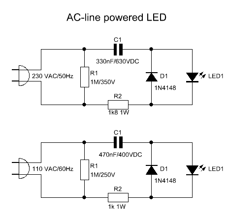


 Led's commonly works only in DC, so we have to convert the alternating
current to direct current and step down to a safe value before applying
to the led sequence.
Led's commonly works only in DC, so we have to convert the alternating
current to direct current and step down to a safe value before applying
to the led sequence.
Led's commonly works only in DC, so we have to convert the alternating
current to direct current and step down to a safe value before applying
to the led sequence.
Led's commonly works only in DC, so we have to convert the alternating
current to direct current and step down to a safe value before applying
to the led sequence.


P1_____________22K  Log. Potentiometer

R1_____________22K  1/4W Resistor
R2,R3_________100K  1/4W Resistors
R4_____________47K  1/4W Resistor
R5______________2K2 1/4W Resistor (See Notes)
R6______________6K8 1/4W Resistor
R7_____________22K  1/2W Carbon or Cermet Trimmer
R8______________2K7 1/4W Resistor

C1,C6_________100nF  63V Polyester or Ceramic Capacitors
C2,C3__________10µF  63V Electrolytic Capacitors
C4_____________22µF  25V Electrolytic Capacitor
C5_____________22nF  63V Polyester or Ceramic Capacitor
C7____________470µF  25V Electrolytic Capacitor

Q1____________BC547  45V 100mA NPN Transistor

IC1_________TDA7052  Audio power amplifier IC

SW1____________SPST  miniature Switch

MIC____________Miniature electret microphone

SPKR___________8 Ohm Loudspeaker

Screened cable used
Parts List
R1______________47K   1/4W Resistor
R2_______________4K7  1/4W Resistor
R3______________22K   1/4W Resistor
R4_______________1K   1/4W Resistor
R5,R12,R13_____330R   1/4W Resistors
R6_______________1K5  1/4W Resistor
R7______________15K   1/4W Resistor
R8______________33K   1/4W Resistor
R9_____________150K   1/4W Resistor
R10____________500R   1/2W Trimmer Cermet
R11_____________39R   1/4W Resistor
R14,R15___________R33 2.5W Resistors
R16_____________10R   2.5W Resistor
R17_______________R22   5W Resistor (wirewound)

C1_____________470nF   63V Polyester Capacitor
C2_____________470pF   63V Polystyrene or ceramic Capacitor
C3______________47µF   63V Electrolytic Capacitor
C4,C8,C9,C11___100nF   63V Polyester Capacitors
C5______________10pF   63V Polystyrene or ceramic Capacitor
C6_______________1µF   63V Polyester Capacitor
C7,C10_________100µF   63V Electrolytic Capacitors

D1___________1N4002   100V 1A Diode
D2_____________5mm. Red LED

Q1,Q2,Q4_____MPSA43   200V 500mA NPN Transistors
Q3,Q5________BC546     65V 100mA NPN Transistors
Q6___________MJE340   200V 500mA NPN Transistor
Q7___________MJE350   200V 500mA PNP Transistor
Q8___________IRFP240  200V 20A N-Channel Hexfet Transistor
Q9___________IRFP9240 200V 12A P-Channel Hexfet Transistor


