Saturday, May 4, 2013

Ca Horn for 6 -12V dc supply

Circuit diagram


 parts list

R1______________68K  1/4W Resistor
R2_______________2K2 1/4W Resistor
R3______________56K  1/4W Resistor
R4_______________3K3 1/4W Resistor
R5,R6____________4K7 1/4W Resistors
R7______________10K  1/2W Trimmer Cermet or carbon

C1,C2___________22nF  63V Polyester Capacitors
C3,C5__________100nF  63V Polyester Capacitors
C4_______________1nF  63V Polyester or Ceramic Capacitor
C6_____________220µF  25V Electrolytic Capacitor

IC1,IC2_________7555 or TS555CN CMos Timer ICs
IC3__________TDA7052  Audio power amplifier IC (See Notes)

SPKR___________8 Ohm  Loudspeaker (See Notes)


This circuit reproduces the sound of modern car horns. It was mainly designed for models and toys but, using a high output power audio amplifier IC, it can be used also in more demanding projects.

Circuit operation

To obtain a realistic car horn sound, two different tones mixed together are necessary and the interval they will form should be a so called minor third (in musical terms).
This is implemented by two 7555 CMos Timer ICs wired as astable multivibrators and generating a square wave of about 440Hz and 523Hz respectively. These frequencies should be quite precise, so the uncommon values necessary for the timing resistors are obtained by wiring two standard value resistors in series.
The square wave frequencies generated by IC1 (440Hz) and IC2 (523Hz) are mixed through R5 and R6 and shaped by C3, C4 and R7 in order to obtain a more realistic tone. The resulting composite audio signal is finally sent to the audio power amplifier IC3 which, in turn, drives the loudspeaker. R7 should be adjusted to obtain a satisfactory output level.

Notes:

  • The loudspeaker can be of any shape and diameter. Obviously it must withstand a power of at least 1 Watt if the TDA7052 Audio power amplifier IC is used.
    In any case, try a good sized device, in order to obtain best results.

LEDs Lamps Sequencer circuits

Very simple, versatile modular design

No limits to the number of modules used in the ring

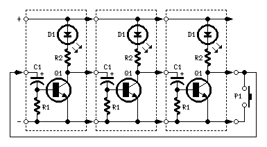
     Circuit diagram 1


    Circuit diagram 2

parts list.

R1______________1K5  1/4W Resistor
R2____________680R   1/4W Resistor (Optional, see text)

C1_____________47µF   25V Electrolytic Capacitor

D1_____________LED  any type

Q1___________BC337    45V 800mA NPN Transistor

P1_____________SPST Pushbutton

LP1____________Filament Lamp 12 or 24V (See text)
 
 
The purpose of this circuit was to create a ring in which LEDs or Lamps illuminate sequentially. Its main feature is a high versatility: you can build a loop containing any number of LEDs or Lamps, as each illuminating device has its own small circuit.
The diagrams show three-stage circuits for simplicity: you can add an unlimited number of stages (shown in dashed boxes), provided the last stage output was returned to the first stage input, as shown.
P1 pushbutton purpose is to allow a sure start of the sequence at power-on but, when a high number of stages is used, it also allows illumination of more than one LED or Lamp at a time, e.g. one device illuminated and three out and so on.
After power-on, P1 should be held closed until only the LED or Lamp related to the module to which the pushbutton is connected remains steady illuminated. When P1 is released the sequencer starts: if P1 is pushed briefly after the sequence is started, several types of sequence can be obtained, depending from the total number of stages.

Notes:

  • If one LED per module is used, voltage supply can range from 6 to 15V.
  • You can use several LEDs per module. They must be wired in series and supply voltage must be related to their number.
  • Using 24V supply (the maximum permitted voltage), about 10 LEDs wired in series can be connected to each module, about 7 at 15V and no more than 5 at 12V.
  • The right number of LEDs can vary, as it is depending by their color and brightness required.
  • Using incandescent lamps, voltage supply can range from 9 to 24V. Obviously, the bulb voltage rating must be the same of supply voltage.
  • In any case, bulbs may also be wired in series, e.g. four 6V bulbs wired in series can be connected to each module and powered by 24V supply.
  • If you intend to use bulbs drawing more than 400mA current, BC337 transistors should be substituted by Darlington types like BD677, BD679, BD681, 2N6037, 2N6038, 2N6039 etc.
  • As Darlington transistors usually have a built-in Base-Emitter resistor, R1 can be omitted, further reducing parts counting.
  • Sequencer speed can be varied changing C1 value.
  • A similar design appeared in print about forty years ago. It used germanium transistors and low voltage bulbs. I think the use of LEDs, silicon transistors, Darlington transistors and 24V supply an interesting improvement..
 

Nokia X2-00 Speaker Solution.

Nokia X2-00 Speaker Solution


                                                      Nokia X2-00 Speaker Solution..

Dual rail Variable DC Power Supply Circuit

 Dual rail Variable DC Power Supply  Circuit


* The circuit can be placed into the existing Variable DC Power Supply metal cabinet.

* Q1 and Q2 must be mounted on heatsinks.

Usually, bolting them to the metal case (through insulating washers etc.) proved effective.

* The full ±15V output can be achieved only if the secondary winding of the supply Transformer used in the Variable DC Power Supply is rated at 48V minimum (center tapped).

* When using this circuit, please set the Current-limit control (P1) of the Variable DC Power Supply to any value comprised in the 50mA - 1A range but not higher.

* The second Op-amp (IC1B) contained in the LM358 chip was not used, but its input pins were tied to the negative supply and the output was left open.


DC Power Supply Dual-rail Variable Part list:

R1 = 4.7K-1/2W
R1 = 4.7K-1/2W
C1 = 100nF-63V
C2 = 220µF-25V
C3 = 220µF-25V
C4 = 100nF-63V
C5 = 100nF-63V
Q1 = BD437
Q2 = BD438
IC1 = LM358

10 Amp 13.8 Volt Power Supply Circuit..


10 Amp 13.8 Volt Power Supply Parts List :

R1 1.5K ¼ Watt Resistor (optional, tie pins 6 & 5 of IC1 together if not used.)
R2,R3 0.1 Ohm 10 Watt Resistor (Tech America 900-1002)
R4 270 Ohm ¼ Watt Resistor
R5 680 Ohm ¼ Watt Resistor
R6,R7 0.15 Ohm 10 Watt Resistor (Tech America 900-1006)
R8 2.7K ¼ Watt Resistor
R9 1K Trimmer Potentiometer (RS271-280)
R10 3.3K ¼ Watt Resistor
C1,C2,C3,C4 4700 Microfarad Electrolytic Capacitor 35 Volt (observe polarity)
C5 100 Picofarad Ceramic Disk Capacitor
C6 1000 Microfarad Electrolytic Capacitor 25 Volt (observe polarity)
IC1 LM723 (RS276-1740) Voltage Regulator IC. Socket is recommended.
Q1 TIP3055T (RS276-2020) NPN Transistor (TO-220 Heat Sink Required)
Q2,Q3 2N3055 (RS276-2041) NPN Transistor (Large TO-3 Heat Sink Required)
S1 Any SPST Toggle Switch
F1 3 Amp Fast Blow Fuse
D1-D4 Full Wave Bridge Rectifier (RS276-1185)
T1 18 Volt, 10 Amp Transformer Hammond #165S18 (Digi-Key HM538-ND)

                                        10 Amp 13.8 Volt Power Supply Circuit

Popular Posts