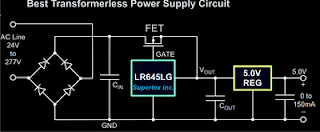
In short the circuit diagram may be understood in the following manner:
- The high voltage AC mains is rectified by the bridge configuration using four diodes at the input.
- The rectified voltage is smoothed by the filter capacitor introduced just after the bridge network.
- The rectified, filtered high voltage is fed to the IC LR645LG, which effectively reduces the voltage to 15 volts at 3 mA.
- The FET pulls the 3 mA current output to 150 mA and feds it to the next stage which incorporates the 5 volt regulator stage.
However one big drawback of eliminating the use of a transformer is the DANGER of high voltage shock that actively hangs with all the naked points of the circuit. Therefore extreme caution must be exercised while building and testing this circuit and other attached circuits.
Parts List
Diodes - 1N4007
Input Capacitor - 4.7uF/400V,
Output Capacitors are 1uF/25V
ICs are LR645LG and 7805,
FET - DN2540N5


