Monday, May 13, 2013

78S09 9 Volt 2 Amp Power Supply

 All the work is done by the regulator. The 78S09 can deliver up to 2 amps continuous output whilst maintaining a low noise and very well regulated supply.
The circuit will work without the extra components, but for reverse polarity protection a 1N5400 diode is provided at the input, extra smoothing being provided by C1. The output stage includes C2 for extra filtering, if powering a logic circuit than a 100nF capacitor is also desirable to remove any high frequency switching noise.

78S09 9 Volt 2 Amp Power Supply 

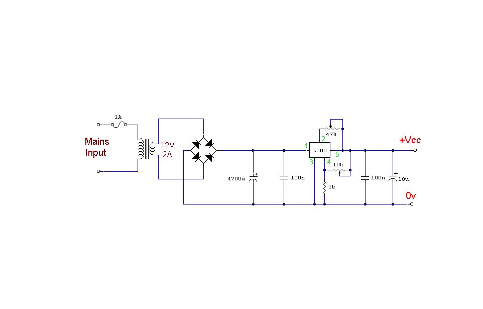
L200 Variable Power Supply Circuit.

 L200 voltage regulator, this power supply has independent voltage and current limits. The mains transformer has a 12volt,2 amp rated secondary, the primary winding should equal the electricity supply. The 10k control is adjusts voltage output from about 3 to 15 volts, and the 47 ohm control is the current limit. This is 10mA minimum and 2 amp maximum. Reaching the current limit will reduce the output voltage to zero.
Power Supply Circuit.

DS1669 Digital Volume Control circuits.

This circuit is used for replacing your manual volume control in a stereo amplifier. In this circuit, push-to-on switch S1 controls the forward (volume increase) operation of both channels while a similar switch S2 controls reverse (volume decrease) operation of both channels.
A readily available IC from Dallas semiconductor, DS1669 is used here.


Sunday, May 12, 2013

LM7805C uses UPS Power Supply.

 UPS Power Supply circuit can be use for regulated and unregulated voltages with different regulators and batteries. For 15-volt regulated supply tariffs to use two 12 volt batteries in series and the 7815 controller. There are a lot of flexibility in the circuit.

 
circuit diagram


TDA7375A IC Amplifier Circuits..

4 channel amplifier uses an IC TDA7375A and capable of producing power 18watt output for each channel. TDA7375A amplifier circuit can be used to make 2 channel stereo configuration is often applied to sound systems in cars. That is 1 channel stereo for the front and 1 channel stereo for the the rear. Source voltage needed for this amplifier is a 12VDC-15VDC. Amplifier circuit with IC TDA 7375A is very simple and easy to make.

Saturday, May 11, 2013

600 Watt Mosfet Power Amplifier Circuits.

Here is a circuit Power Amplifier with output power of more than 600 Watt speakers with impedance of 4 Ohm. Power Amplifier circuit with high power uses n-channel MOSFETs 6 in the output stage alone is giving about 400Watt power. And to make more than 600Watt need to use 12 N-Channel MOSFETs. One of the construction sequence to produce more output power of 900W using 12 IRFP460 MOSFET. Here is a Power Amplifier Circuit Diagram, and the Power Supply is suited for this amplifier. I also include a PCB Layout Design for the power amplifier and its power supply, you can see below. 

Adjustable 0-30V 2A Laboratory DC Power Supply circuits.

Adjustable 0-30V 2A Laboratory DC Power Supply


 PCB of Cheap adjustable 0-30V 2A Laboratory DC Power Supply

This 0-30V power supply is the variable voltage Regulator at 2A max, by used IC-723 for control volt stable regulated. The 2N3055 power transistor for boost up current to 2amp.
It suitable for general electronics work shop. Because it is a simple circuit and easy circuit. In addition to this has the over current protection as well.
This circuit is designed using LM723 voltage regulators IC –DIP 20pin maintain a constant voltage, and a power transistor as the way through the current to can be used up as wanted.
The circuit was designed also with overload protection or short circuit in the output. The amount of current flow will not exceed the set. Because it is monitored constantly by R4.
When the current flows through the R4, until the 0.6V voltage drop across it. Making Q3 runs short the bias voltage between the base-emitter of Q2, it stopped working. Now, the Q1 stop working because does not has the bias voltage to base pin its, The output voltage is zero or down quite a close to zero.
The potentiometer VR1 acts as adjust the voltage that enter to the LM723 for the volt output by you want. By the our circuit can adjust the voltage output from 0V to 30V.
In use real, because the properties of the transistors used and values error of each device. Therefore, if the circuit can not be supply up to 2 A. Try changing the value of R4 is a lower value, until has the maximum current desired. Should be to use transformer 3A. The Transistor to Hold Heat sink as well.


Popular Posts