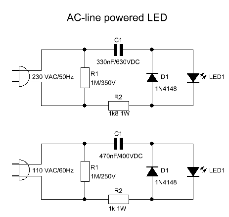
A long time ago I found a little schematic on internet on how to
power a LED from an AC Line.
I tested and modified it a little so now it works great.
You could use it as an power-on indicator for your waterpump or so. Also it can be used with whatever LED-color you like.
I tested and modified it a little so now it works great.
You could use it as an power-on indicator for your waterpump or so. Also it can be used with whatever LED-color you like.
I included the schematics for US or canadian 110-120V 60Hz AC
lines, as well as european or australian 230-240V 50Hz AC lines.
The capacitor is used to drop the voltage and the resistor to limit the inrush current.
Since the capacitor passes the current in both directions, a small diode is connected in parallel with the LED to provide a path for the negative half cycle and to limit the reverse voltage across the LED. The resistor value was chosen to limit the worst case inrush current to about 150mA which will drop to less than 30mA in a millisec as the capacitor charges.
The 0.47uF capacitor has an impedance of 5600 Ohms at 60Hz so the LED current is about 20mA half wave, or 10mA average (for the 230V version the impedance of the 0.33uF capacitor is 9600 Ohms at 50Hz which gives you also a LED current of about 10mA average)
Z = 1 / 2*Pi*f*C
Z = Impedance in Ohms
Pi = 3.14
f = frequency in Hertz
C = capacity in Farads)
C = capacity in Farads)
The capacitor must be a non-polarized type with a voltage rating of at least 250VDC or preferably more for 110V AC-lines, or at least 400VDC or preferably more for 230V AC-lines.
Resistor R1 discharges capacitor C1 in a few seconds after AC-line is disconnected. Remember that R1 must be able to withstand the full half wave peak AC-line voltage.
IMPORTANT: The circuit is powered from the AC line, so I will not be held responsible in any way for burned fingers, or melted fuses in your house. Isolate all connections with heat shrink.
Electronics Circuit Application


No comments:
Post a Comment