Sometimes the perfect wi-fi antenna is the one that can be made in an hour's time, from inexpensive parts, and yet enables connections over moderate to long distances. The yagi wi-fi antenna design depicted here is exactly that! It is computer designed, made of wood and wire, and provides high gain and directivity. It is directional - favoring wi-fi signals in one direction and rejecting interference from the sides or behind the antenna. The 15 element wi-fi antenna provides over 15 dB of gain (multiplying your effective radiated power by 31), while the larger 20 element wi-fi antenna provides over 17 dB of gain (multiplying your effective radiated power power by 51). Front to back ratio for both antennas is about 22 dB.
Yagi wi-fi antennas can be rather difficult to make - elements must be precisely cutto the proper length, and spaced at the correct distance from otherelements, or the antenna doesn't work. Before good computer tools were available, a designer used various charts and tables to determine antenna dimensions. These days, however, much of the mind numbing calculation can be carried out in a split second. One excellent tool for crunching design numbers is the yagi antenna modeler, created by Kevin Schmidt (W9CF) and Michael Lee.


The on-line antenna modeler initially starts with several examples tailored for operation in the amateur radio bands. One of the best designs is the classic K1FO yagi. By following a few steps, the antenna can be scaled for the 2.4 Ghz wi-fi 802.11 b/g/n frequencies:
- Start with the 15 or 20 element K1FO 70cm example.
- In the "units" menu, select "Radians."
- In the "conductivity" menu, select "Copper"
- In the "frequency" field, enter 2450 (MHz) for the center of the wi-fi networking band.
- For "Element Diameter", enter 0.08729 (radians).
- Click the "calculate" button.
- In the "units" menu, select "millimeters."
- Note that the element diameter perfectly matches 14 gauge wire!
- In the file menu, select "list elements."
| Element | Length (mm) | Position (mm) |
| 1 (Reflector) | 59.61 | 0.00 |
| 2 (Driven Element) | 58.55 | 18.34 |
| 3 (Director) | 55.20 | 25.75 |
| 4 (Director) | 53.62 | 39.51 |
| 5 (Director) | 52.38 | 58.55 |
| 6 (Director) | 51.68 | 82.19 |
| 7 (Director) | 50.97 | 109.70 |
| 8 (Director) | 50.62 | 140.74 |
| 9 (Director) | 50.26 | 174.60 |
| 10 (Director) | 49.91 | 210.94 |
| 11 (Director) | 49.56 | 249.38 |
| 12 (Director) | 49.21 | 289.60 |
| 13 (Director) | 48.85 | 331.39 |
| 14 (Director) | 48.68 | 374.25 |
| 15 (Director) | 48.50 | 418.52 |
| Element | Length (mm) | Position (mm) |
| 1 (Reflector) | 59.96 | 0.00 |
| 2 (Driven Element) | 58.91 | 18.34 |
| 3 (Director) | 55.56 | 25.75 |
| 4 (Director) | 53.97 | 39.51 |
| 5 (Director) | 52.73 | 58.55 |
| 6 (Director) | 52.03 | 82.19 |
| 7 (Director) | 51.32 | 109.70 |
| 8 (Director) | 50.97 | 140.74 |
| 9 (Director) | 50.61 | 174.60 |
| 10 (Director) | 50.26 | 210.94 |
| 11 (Director) | 49.91 | 249.38 |
| 12 (Director) | 49.56 | 289.60 |
| 13 (Director) | 49.21 | 331.39 |
| 14 (Director) | 49.03 | 374.25 |
| 15 (Director) | 48.85 | 418.52 |
| 16 (Director) | 48.68 | 463.67 |
| 17 (Director) | 48.50 | 509.70 |
| 18 (Director) | 48.32 | 556.26 |
| 19 (Director) | 48.15 | 603.53 |
| 20 (Director) | 47.97 | 651.32 |
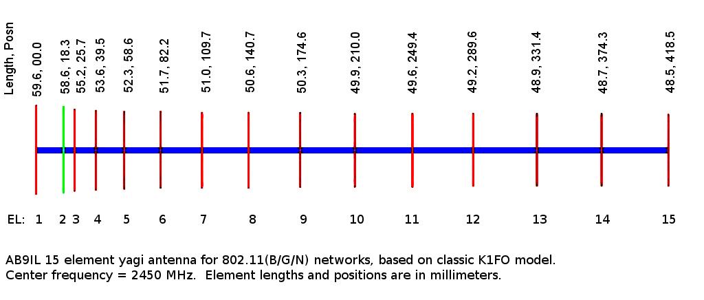
Below is a graphic, meticulously adapted by AB9IL from the modeler, which shows element lengths and positions along the boom, measured from the reflector (location zero millimeters). Note that the driven element is depicted in green, and for the wi-fi yagi project, will be a folded dipole. Why a folded dipole? It provides a good impedance match to coaxial cable when used as the yagi wi-fi antenna's driven element. In free space, a folded dipole has a 300 ohm impedance at resonance, but the impedance drops drastically when parasitic elements are brought into close proximity.

There are crap copies of this antenna, pimped on crap peddling websites, which fail to perform. Use the instructions given here and avoid those cheap imitations!
YAGI Wi-Fi ANTENNA PARTS LIST:
- A 1.2 meter length of 14 AWG bare, solid copper wire.
- One wooden square, 1 cm per side, 50 cm long (70 cm for the 20 element antenna).
- Wire cutters.
- Metric ruler.
- Drill, with 1.6 mm (1/16") bit.
- Printed or written template with antenna dimensions.
- Ball point pen or fine felt tipped marker.
YAGI Wi-Fi ANTENNA CONSTRUCTION:
Assemble the yagi wi-fi antenna following the steps below, starting with preparation of the boom, followed by mounting the elements. After the elements are mounted, a suitable connector is added, and the antenna is tested over-the-air. Keep in mind that it can be connected to most usb wireless adapters by cutting the circuit board antenna trace and patching in a pigtail feeding the antenna.- Draw a line as accurately as possible down the center of one side of the wooden boom.
- Mark the boom centerline 5 cm from one end. This is the "zero location," where the director element will be mounted.
- Continue down the boom, carefully marking the locations of each element on the centerline.
- Carefully drill through the boom at each element's location. Make sure to drill straight through the boom, emerging on the other side still centered and perpendicular.
- Cut one element at a time, carefully measuring each element before and after cutting, trimming as necessary for proper length. File the wire ends and make sure the lengths are as accurate as possible!
- Press elements through the boom, centering each before moving to the next element.
Element positions marked
 on the yagi wi-fi antenna boom. on the yagi wi-fi antenna boom. |
The reflector element
after mounting. |
- For the driven element, cut a 130 mm length of wire, and make a 180 degree bend 30 mm from one end. Mount in boom, then make a bend 30 mm from other end. Adjust as necessary to create a folded dipole just under 59 mm in length with 5 mm spacing.
- Double check all elements, making sure all are centered and parallel.
- Attach a pigtail (or connector) to open ends of folded dipole.
|
Folded dipole prior
to mounting in antenna boom. |
 before the last bend. |

 Closeup of the wi-fi yagi feedpoint. Keep the leads short! |


No comments:
Post a Comment